I finally finished decoding all the messages between my alarm panel and the keypad.
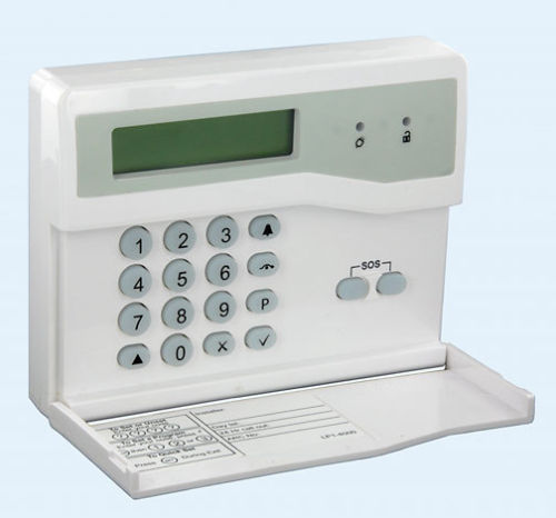
The alarm is an Accenta Mini G4 from Honeywell. The keypads can be found on ebay for less than £30. Cheap enough to use with a small project – though it seems outrageous when you think that you can get a Raspberry Pi for the same money.
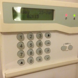
Connections
Inside it has 6 connections:
- +12v
- Ground
- Tamper +
- Tamper –
- Sound
- Comms
The tamper connections just connect to a switch in the back of the case so that the circuit is broken if it’s opened or taken off the wall.
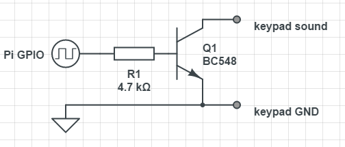
The sound connection drives a mini piezo speaker. The connection floats to +12v and you need to sink about 40mA per keypad to drive it. I used the circuit on the right to to connect it to a raspberry pi gpio pin but it didn’t sound very good. In fact it sounded like a strangled cat. I’m not sure if that’s caused by wiring-pi’s tone generation competing for processor time or if I need to add a low pass filter in there to smooth out the square wave. – If anyone can suggest a better driver circuit please let me know.
The comms connection is for an RS-485 based serial bus running at 1200 baud. The connection floats to +5v and anything transmitting pulls it down to send a 0. The pull up resistor seems to be about 10kΩ so assuming up to 6 devices on the bus each driver needs to sink 3mA.
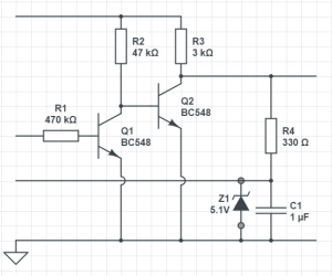
This is the driver circuit I’ve used to interface it to a UART that can accept 5v input. This will pull the line down when the UART sends a 0 but otherwise let it be pulled up by the 3k resistor and allow other devices to transmit. The capacitor is to smooth out noise as the wire could be quite long. The zener is there to protect the UART from possible shorts with the +12 line during installation or maintenance. Any suggestions for improvement welcome.
The serial protocol works like this:
When a key is pressed the keypad sends 3 bytes:
K <key> <checksum>
The K is an address byte marked with the 9th (parity) bit set to 1. <key> is the ascii value of the key pressed. The <checksum> is the sum of the preceding 2 bytes modulo 256.
Then there are 2 different types of message you can send to the keypad:
P controls the leds:
P <zones> <leds> <checksum>
<zones> probably sets the 8 zone leds – but the LCD keypad doesn’t have them. <leds> sets the power (bit-3) and unset (bit-0) leds. If you have them I think bits 1 & 2 control the tamper and sos leds. <checksum> is the sum of the preceding 3 bytes mod 256.
L controls the LCD screen
L <length> <message...> <checksum>
<length> is the length of the <message…> part, <message…> is ascii text to display with a few special characters and <checksum> is the sum of all preceding bytes mod 256.
Then within the LCD text:
- 0x06 (\f) clears the screen and moves the cursor to the top left.
- 0x04 means that the following byte is a control character as understood by a Hitachi HD44780 compatible LCD controller. (Just by chance I’d used one of these in a previous project and recognised the codes.) This article from Everyday Electronics explains all.

Hi, what baud rate is the serial line running at?
LikeLike
1200 – I’ve updated the text thanks
LikeLike
Did you ever look at the Honeywell Easy Set [SS/01] somewhere that arms and disarms the Accenta G panel over the same comms interface, curious as to how for a reverse engineering project.
LikeLike
Sorry I don’t have one of these but it would be interesting to know how they worked.
LikeLike
Thanks for a very useful article!
These are now getting hard to find, I was thinking of creating one using an ESP32 microcontroller. When you say K is the address byte in the transmitted message, what did you mean by that – on first reading I had assumed it was “K” in ascii, but I am now doubting myself!
Also looks like the bytes send/received are 9 bit parity – is the parity even, odd, mark or space?
Thanks again!
LikeLike
Yes super hard to find now. I have an update in the pipeline that uses a Honeywell CP083 lcd keypad with a USP to RS485 adaptor. Much easier to find and to use.
the <K> is not a “K”, it’s the ID of the device that should receive the message
parity is 1 for the ID bite and 0 for the rest. This is tricky to do with some UARTS, you have to make sure all the data is sent before changing parity.
LikeLike