There isn’t any easy way to use 9-Bit RS-485 mode ascii in linux. This mostly comed down to the fact that the posix standard only specifies even or odd parity not mark or space. There are a few different ways
Extending the pigpio gpioWaveAddSerial() function for 9-bit – This sounds a bit like glorified bit-banging. I’ve heard that it uses quite a lot of cpu time and there isn’t any satisfactory way to read data. Still it looks like some people are making great progress.
Simulating mark or space parity by setting even or odd parity according to the byte being sent. This has some appeal to me because all the hard work can be done in software. Provided that the parity settings can be changed without causing any significant sending delay of course. Apparently it works. I might give it a try later.
Using an external UART that’s actually capable of doing RS-485 out of the box -This is what I’ve done.
The UART I found was the SC16IS750. It will connect to the Raspberry Pi’s I2C or SPI bus, and will do just about any serial mode you can think of over a huge range of speeds. Spark fun also sell one on a handy breakout board.
SC16IS750 breakout board from SparkFun – notice the extra wire required to use the IRQ pin.
The datasheet is huge but driving it mostly boils down to reading and writing registers via the I2C or SPI bus. The only thing that wasn’t clearly explained was that you have to let the output buffers drain before switching between writing 9-bit address and data bytes.
I’ve written a python class which makes it easy to read and write messages. The proof is here. The code is finally in github here https://github.com/mikeyg123/pi-alarm
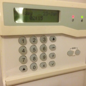
I finally finished decoding all the messages between my alarm panel and the keypad.
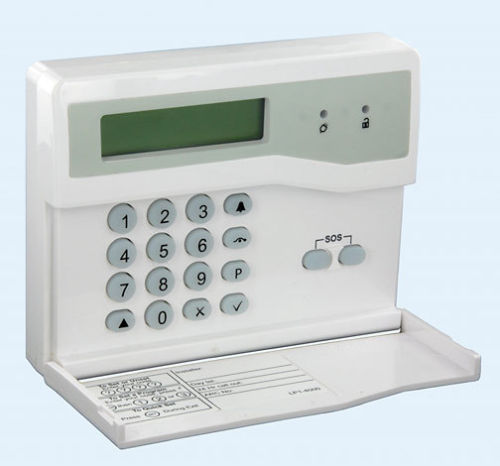
The alarm is an Accenta Mini G4 from Honeywell. The keypads can be found on ebay for less than £30. Cheap enough to use with a small project – though it seems outrageous when you think that you can get a Raspberry Pi for the same money.
Connections
Inside it has 6 connections:
+12v
Ground
Tamper +
Tamper –
Sound
Comms
The tamper connections just connect to a switch in the back of the case so that the circuit is broken if it’s opened or taken off the wall.
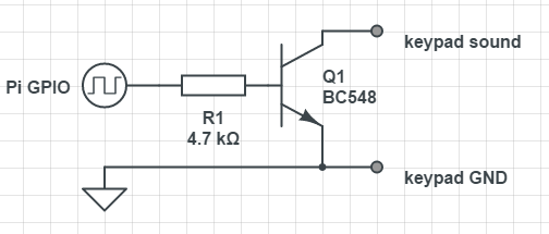
Piezo speaker driver. The BC548 was just the first NPN i found in my spares box.
The sound connection drives a mini piezo speaker. The connection floats to +12v and you need to sink about 40mA per keypad to drive it. I used the circuit on the right to to connect it to a raspberry pi gpio pin but it didn’t sound very good. In fact it sounded like a strangled cat. I’m not sure if that’s caused by wiring-pi’s tone generation competing for processor time or if I need to add a low pass filter in there to smooth out the square wave. – If anyone can suggest a better driver circuit please let me know.
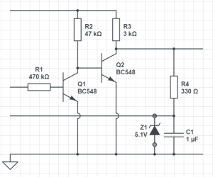
The comms connection is for an RS-485 based serial bus running at 1200 baud. The connection floats to +5v and anything transmitting pulls it down to send a 0. The pull up resistor seems to be about 10kΩ so assuming up to 6 devices on the bus each driver needs to sink 3mA.
Serial bus line driver connects the UART Tx and Rx on the left to the shared bus on the right.
This is the driver circuit I’ve used to interface it to a UART that can accept 5v input. This will pull the line down when the UART sends a 0 but otherwise let it be pulled up by the 3k resistor and allow other devices to transmit. The capacitor is to smooth out noise as the wire could be quite long. The zener is there to protect the UART from possible shorts with the +12 line during installation or maintenance. Any suggestions for improvement welcome.
The serial protocol works like this:
When a key is pressed the keypad sends 3 bytes:
K <key> <checksum>
The K is an address byte marked with the 9th (parity) bit set to 1. <key> is the ascii value of the key pressed. The <checksum> is the sum of the preceding 2 bytes modulo 256.
Then there are 2 different types of message you can send to the keypad:
P controls the leds:
P <zones> <leds> <checksum>
<zones> probably sets the 8 zone leds – but the LCD keypad doesn’t have them. <leds> sets the power (bit-3) and unset (bit-0) leds. If you have them I think bits 1 & 2 control the tamper and sos leds. <checksum> is the sum of the preceding 3 bytes mod 256.
L controls the LCD screen
L <length> <message...> <checksum>
<length> is the length of the <message…> part, <message…> is ascii text to display with a few special characters and <checksum> is the sum of all preceding bytes mod 256.
Then within the LCD text:
0x06 (\f) clears the screen and moves the cursor to the top left.
0x04 means that the following byte is a control character as understood by a Hitachi HD44780 compatible LCD controller. (Just by chance I’d used one of these in a previous project and recognised the codes.) This article from Everyday Electronics explains all.
Since I haven’t been able to find any suitable raspberry-pi compatible keypad I thought I’d try and use the existing home alarm keypad. All I have to do is listen to the messages going between the existing alarm and keypad, decode the message protocol and build something that can communicate with it. What could be simpler.
So I attached a pair of wires to the signal and ground connections so I could connect my excellent Open Logic Sniffer. Then with my laptop balanced on a chair I stood in the hallway pressing buttons trying to see a signal.
After a bit of trial and error I got this:
Since you can have multiple keypads communicating over a single wire I had assumed that it would use the I2C protocol. However trying a few of the protocol analysers in the OLS client the UART analyser pulled out some recognisable text. Along with a lot of errors.
The errors seemed to screw up the ols display so the decoded text didn’t line up with the signal trace any more. This made it really tricky to work out what was happening and I ended up spending ages with a ruler on the screen to count bits. I eventually figured out that the message was sent with the parity bit zero except for the first byte of each message.
Then after all this effort a bit of googling revealed that this is actually a standard called RS-485
The next step is to attach it to a serial port so I can read out the text a bit more easily.
A few years ago, when we started on the home renovation project, I installed an alarm system. It’s got sensors in several rooms, switches on some doors, a keypad by the door for arming and disarming and a loud bell on the wall outside. Occasionally someone comes in and forgets the code but on the whole it works.
There are a couple of things that became obvious to me while I set it up:
It’s really simple – it’s clearly nothing more than a cheap microcontroller and some fairly simple software to ring a bell if a circuit gets broken.
It’s not very useful – having the blinking light on the box outside might deter the casual thief but if someone actually does break in all it can do is ring a bell and annoy the neighbours.
So let’s build a better one.
Ideally one that:
Tells us if someone breaks in – no matter where we are.
Give us a chance to cancel a false alarm before it starts to annoy the neighbours.
Lets us set and unset it from our phones
Send us a message if someone goes out without closing all the doors (instead of displaying a cryptic message on an LCD and a slightly different pattern of beeps).
Will arm itself if everyone goes out without remembering to do it.
Has a night mode that doesn’t wake everyone up when it’s set and unset.
Will run for a few days without mains electricity.
Doesn’t completely rely on my home internet connection.
Looking around on the internet there are a few projects which will allow you to hook up a few switches to something that sends you a message – but nothing that does all the above or works as a drop in replacement for a the existing system. If you know of anything please let me know.
Right now my plans revolve around a raspberry pi hooked up via the I2C or SPI bus to a few ADCs that can measure the resistance of the sensor circuits.
Twitter, email or sms messages can be sent & received via my home internet connection. A 3G USB stick can act as a backup internet connection.
The existing alarm runs off a 12v lead-acid battery when the power fails so the new one can do the same.
One more thing – it has to have some way to control it if all our phones are flat and there’s no internet connectivity or mains electricity. This means it has to have some sort of keypad that everyone can use. I can’t find anything that easily plugs into a raspberry pi via 10m of alarm wire and looks good enough to permanently install next to the front door. Ideally I could re-use the existing one but I have no idea how to interface to it.


You must be logged in to post a comment.